Sunday, May 7, 2017

Rudder Pedals

Today was interesting day. I got to work on something that is actually a functional part. There are a lot of little pieces which need to be fabricated to make these work. Started with the actual pedal plates. These were pre-cut out.


Then stiffeners for each side.


Then they get drilled.


Do that times 4.


Then fit the side control arms.


Debur then rivet. Install on the pedal assembly.


Another Shot.


Install the master cylinders.


Final Fit.

Friday, May 5, 2017

More Parts that no one will ever see. . .

Some more angle brackets and more gussets and just stuff. Each of these has to be cut out from stock angle aluminum. Pics for your viewing pleasure.


Thursday, May 4, 2017

Right Side Gusset Drilled


That gusset I made yesterday, today i get to place and drill it.

line up and clamp


Opposite side after drilling

Drill Lower Longerons

Today I drilled the lower longerons. These are the 8 AN3 Bolts which attach the longerons to the lower engine mount. Again this is important as this holds the engine to the plane.

Here is a couple of shots of the task before I begin.


another angle for clarity.


First mark the proper locations behind the firewall.


Used the punch to mark out the lateral location. This must be done exactly correct to maintain the proper edge distance for the holes.


Drilled all holes with a #40 bit.


Up-sized to AN3 (#12)


And repeat on the opposite side.

Wednesday, May 3, 2017

Forward Gusset

This part confused me. Based on the instructions, I have no idea how this fits into the plane. This is one of those times where I just accept the fact that I don't understand and just blindly make the part.


Here is a pic of the instructions for the shape. The two sides get bent in opposite directions.


Traced the part on the sheet and cut out the shape with the Cutoff wheel. Looks pretty good.


Make the two bends by clamping in the bench vice and whacking with a dead blow. I still don't know how or where this fits.


After studying some other builder websites, I got it figured out.


AUX Longerons


Today I fabricated, fitted and drilled the upper middle and lower longerons. These are all cut from angle aluminum.


Monday, May 1, 2017

Holes for Main Gear

Next up is to open up the holes in the forward section floor for the main landing gear. This is done by using a template supplied in the plans and cutting out the oval.

Here is a shot of the template.


Traced template transferred to the floor.


I had a can of purple spray paint sitting right there so that's what happened.


I drilled some starter holes using a speed bit and connected the dots using the jig saw with a metal blade. Finished up with some sand paper and here is the outcome.


And poof, here is a second hole.


Attach Firewall

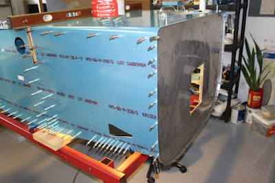
Holy Cow - lots to talk about today!!! Main task for tonight is to line up and drill the Firewall assembly to the fuselage. This not that difficult, just time consuming.

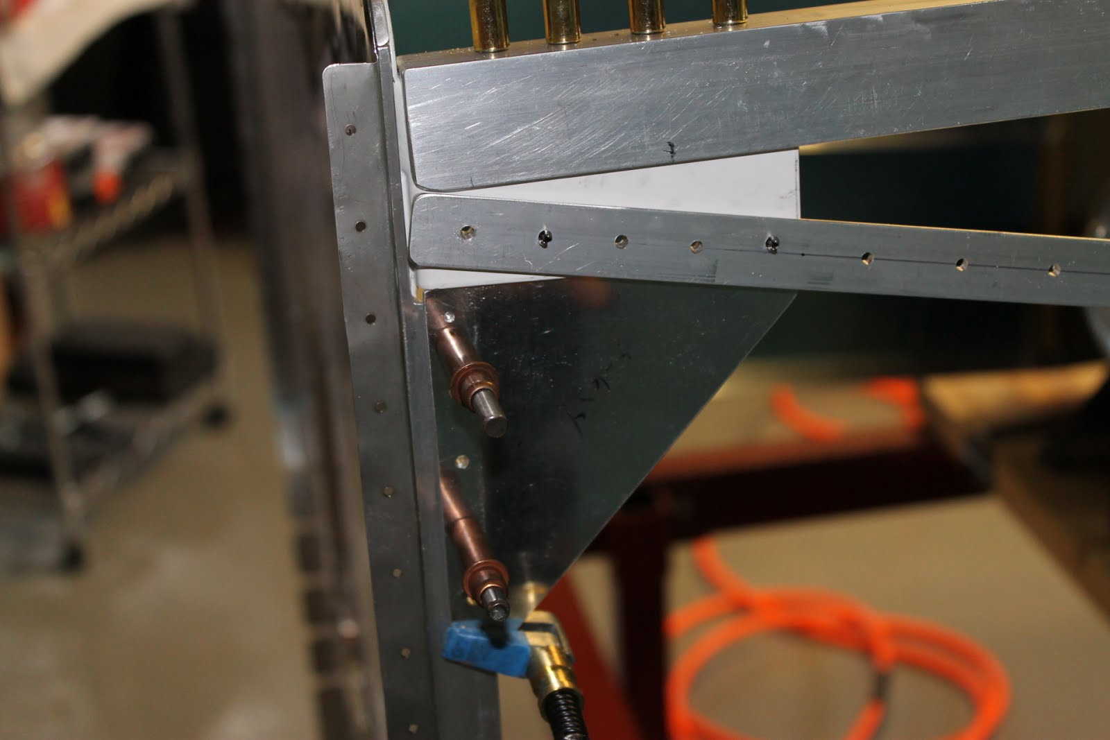
Begin by clamping the engine mount attach brackets to the main longerons. These have to be lined up correctly in order to get proper rivet edge clearance and to make sure the plates are flat against the longeron angle. This is important as this is what holds the engine on the plane. Can't have the flying off somewhere. Hint, the plane is upside down.


once it is lined up correctly, then the holes can be drilled. This is stainless steel. I ended up ruining a drill bit before I was finished. This happened even though I used Boelube on every hole.


Then I can drill the Engine mount attach brackets. (The bronze colored Clecos)


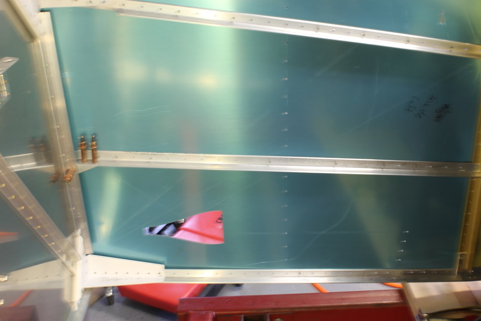
A shot from the inside to confirm that I have the minimun 1/4 inch center to edge clearance.


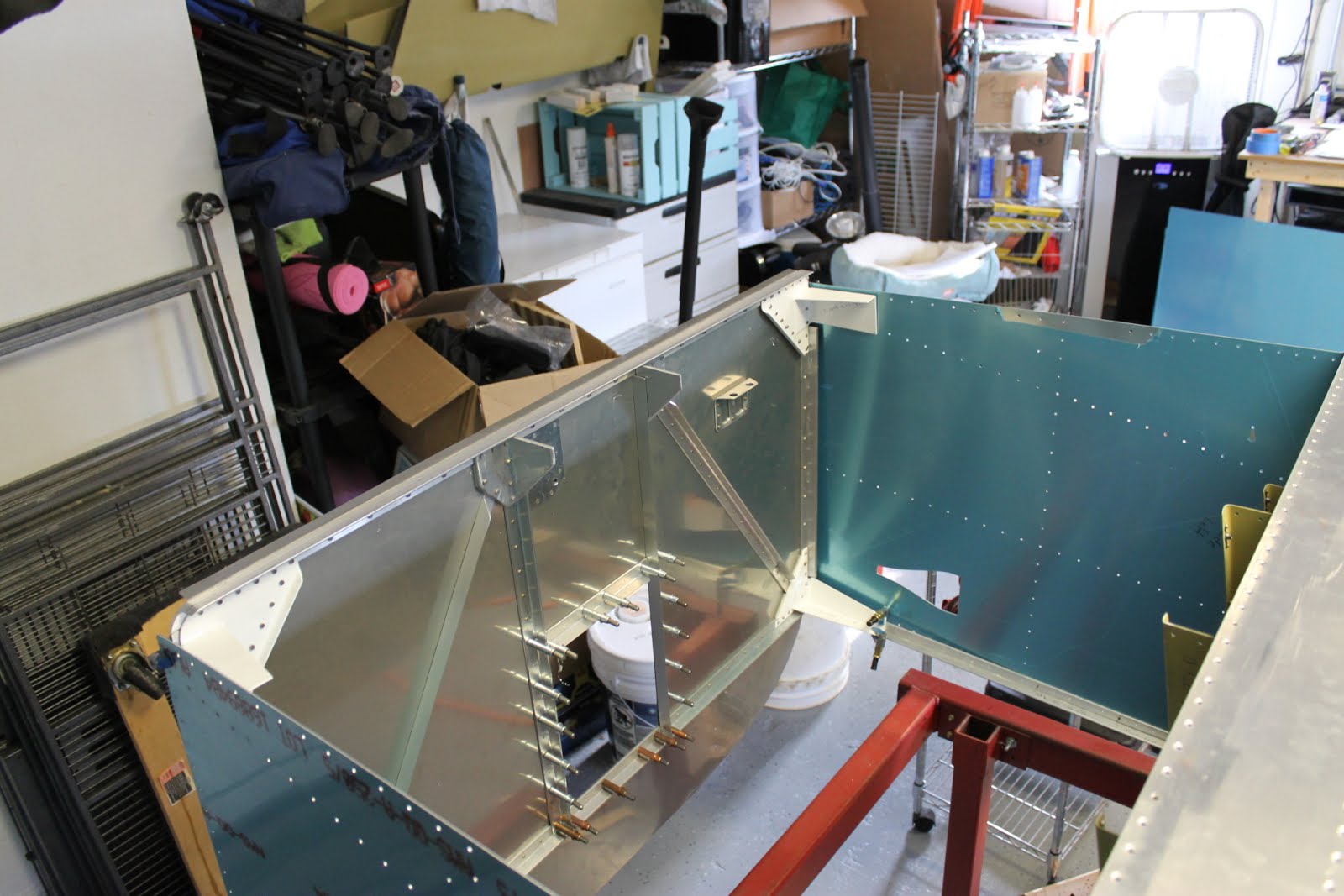
A shot of the whole bracket.