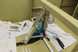
OK, this one I have been thinking about for quite a long time. The H Stab attachment to me seems difficult because there are no predrilled holes. The assembly gets thrown on and you do your best to line things up then clamp and drill. I worked for several hours getting this positioned correctly.

The instructions state that you should measure from the back corner of both sides of the H Stab to a common point on either side on the forward fuselage. The problem here for me is that after deburring the skin on the rear H Stab, there is know way to know if both sides were sanded the same. There could have been more material taken of one side than the other. In this case, there would be no way to measure this as square to the fuse.
So my approach added some criteria to the equation. I first found and marked the center point of the H Stab. I also found and marked the center point of the fuselage rear deck where the H Stab would be mounted. Lining these two marks up ensures that it is at least centered on the rear deck. Clamp!!! Next I measured from both rear H Stab corners per the instructions. I first measured to the top of the 704 bulkhead. After some jockeying, I was able to get the two sides within 1/64 of an inch of the same measurement. This would require a counter clockwise rotation of the H Stab to fix when viewed from the top. Next I measured to the rear of the firewall on both sides. This showed a difference of 1/64 of an inch in the opposite direction, clockwise. Checking several other points, I always came up with the same result, within 1/64 of every measurement but never in the same direction. I must be as close as i can get with this one.
So i ask myself, what is the net effect of being up to 1/64 inch off (I don't care to do the math to figure out how many degrees off, certainly less than 1). Really this is defining the longitudinal plane which the vertical stabilizer will be positioned. If this surface is canted in one direction, the plane will always yaw is the opposite direction as if the rudder will always deflected. This can be corrected with a rudder trim tab if necessary.
*** OK, so I went back and did the math. Lots of math. Pages of math before I came to the conclusion there is no way to accurately measure from the rear corner edge of the H Stab to a point on the center line of the forward fuselage. This poor measurement always skews the calculation. Without even calling support, I can already hear them telling me "Just drill the damn hole!!!"
That is what I did. Clamped and drilled. I know I am within 1/64 inch, but who knows what direction.


